


Chapter 1 Introduction to the Business Communications Manager Platform Hardware 45
Installation and Maintenance Guide
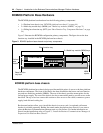
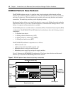
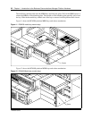
The chassis interior contains the following hardware components:
• 1 x Programed hard drive (or field redundancy upgrade provides an additional hard disk and
RAID controller card) - see “Hard Disk” on page 67.
• 1 x Auto-sensing power supply (standard) - see “Platform Power Supply” on page 65.
• 1 x System cooling fan - see “Cooling Fan” on page 68.
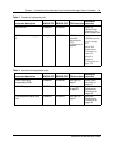
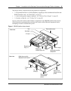
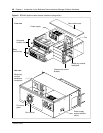
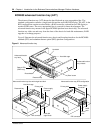
Figure 4 shows the location of the hardware components in the BCM200 platform base chassis.
Nortel Networks recommends that you know the location of the different components before
attempting to install or maintain the system.
Figure 4 BCM200 platform base chassis
Rear view
Base function
tray (x1)
Media bay
module bays (x2)
Power supply
bay
Hard disk bay
(removeable
panel)
Removable cover
Power supply
Hard disk
Fan
Media bay module
backplane
I/O card
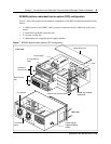
Front view
Fan
exhaust
Rack-mount
adapter anchor
points
Media bay module
backplane connectors