


217
Installation and Maintenance Guide
Chapter 10
Replace Data Cards and Processing Hardware
This chapter describes how to replace data card and processing hardware components.
The following are field replaceable units (FRUs) for the BCM200 and BCM400 platforms:
• Base function tray
• Cards (WAN, MSC, Modem)
• Computer memory
• PEC cards
• Main card CMOS battery
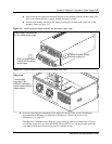
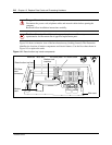
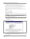
System status LEDs
Ten LEDs on the front of the Business Communications Manager base function tray indicate PCI
card and hardware status.Use the LEDs to determine PCI device status as follows:
• Green LED on: Device is present and the driver is active
• Green LED flashing: Driver is not running
• Green LED off: Device is not present
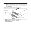
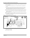
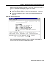
Card Replacement Procedures
For a description of the function of each type of card on the Business Communications Manager
system, refer to “Data networking components” on page 62. The base function tray (BFT) contains
all of the cards described by the replacement procedures.
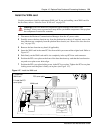
Use the procedures in this section to replace the following cards:
• Wide area network (WAN) card
• Media services card (MSC)
• Modem card
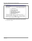
Warning: You must remove all of the connections to the Business Communications
Manager before you power the system down.
Failure to disconnect lines before power down can cause damage to the system.
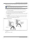
Warning: Protect the hardware components against damage from electro-static
discharge. Always wear a ground wrist strap before you handle components. Always place
the components in static-free container.