


Chapter 13 Install Analog Terminal Adapters 281
Installation and Maintenance Guide
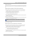
Use this procedure to connect the cable.
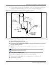
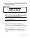
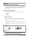
1 Connect one end of a line cord to the ATA2 Terminal jack. Refer to Figure 181.
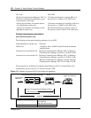
Figure 181 ATA 2 top view
2 Connect the other end to your telephone, modem or FAX.
3 Connect one end of a line cord to the ATA2 Line jack.
4 Connect the other end to an available station port on the Business Communications Manager.
5 For a 120 V or 230 V system, plug the DIN connector of the power supply cord into the power
supply connector receptacle. Plug the adapter into a standard ac outlet.
6 This procedure is complete.
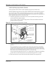
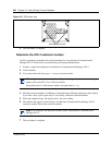
Mount the Business Communications Manager ATA 2
Use this procedure to mount the unit on a wall after the ATA 2 is correctly connected.
1 When using 0.5 mm wire (24 AWG), select a location within 800 m (2,600 ft.) of the Business
Communications Manager system.
2 Allow 12.5 cm (5 in.) clearance for the line jack, terminal jack, and power supply connector.
3 Screw two 4 mm (#8) screws into the wall, 130 mm (5 1/4 in.) away from each other. Leave 6
mm (1/4 in.) of the two screws showing.
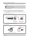
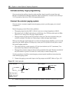
4 Align the slots at the back of the Business Communications Manager ATA 2 unit over the
screws. Push the unit against the wall. The line jack, terminal jack and power supply connector
must be at the top of the Business Communications Manager ATA 2. Refer to Figure 182 on
page 282.
Caution: In North America, the Business Communications Manager ATA 2 must be
powered from a Class 2 power source that is UL and CSA approved.
In Europe, the Business Communications Manager ATA 2 must be powered from a Class
II power source that is CE marked.
=
24 V ~
0.006 A
Terminal jackLine jack Power supply connector receptacle