


Chapter 9 Replace or Upgrade a Power Supply 195
Installation and Maintenance Guide
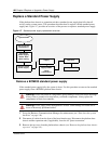
Install a BCM200 standard power supply
Use this procedure to install a functional standard power supply in a BCM200 platform base
chassis. The I/O card must be removed from the platform base chassis before you perform this
procedure. The base function tray must be partially removed.
1 Obtain and use only the power supply recommended by Nortel Networks.
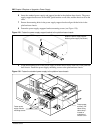
2 Place the new power supply into the platform base chassis.
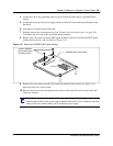
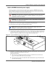
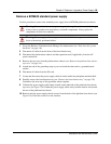
3 Secure the power supply to the platform base chassis. Align the power supply mounting holes
with the chassis holes. Install the chassis screws at the rear of the platform base chassis. See
Figure 121. Do not over-tighten the power supply chassis mounting screws.
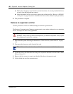
Figure 121 Install the BCM200 power supply chassis screws
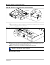
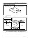
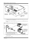
4 Run the P4, P5, P6 power supply cable and the IDE cable to the hard disk. The I/O card is not
installed in the platform base chassis for this step.
Perform the following:
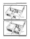
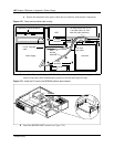
a Route the power cable between the I/O card chassis standoffs in the area shown (see
Figure 122). Run the IDE cable in the same manner.
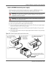
b Tie-wrap the power cable to the hard disk cable. Position the tie-wrap 1/2 inch from the
hard disk cable sheathing.
Warning: Protect the hardware components against damage from electrostatic discharge.
Always wear a ground wrist strap before you handle components. Always place the
components in static-free container.
Warning: Power supply cable management is critical. Cable damage can result due to
loose or incorrectly positioned cables.
Note: Install the power supply carefully. Ensure the power supply cables are not
entangled or crushed against any internal components.