


72 Chapter 1 Introduction to the Business Communications Manager Platform Hardware
P0993133 03
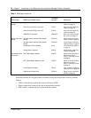
Table 8 Media bay module list
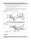
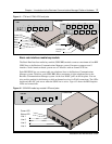
Media bay modules are designed within a common casing, that include the following common
features:
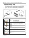
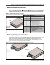
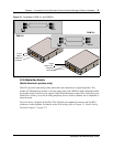
• LEDs: All media bay modules have power and status LEDS.
• Power connections: located at the rear of the media bay module
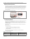
• DIP switches: located at the rear of the media bay module
Module type Media bay module name
Faceplate
acronym Reference
Trunk media bay
module
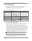
Digital trunk interface DTM Digital trunk media bay
module on page 75
Caller ID trunk (CLID) 4 line trunk CTM 4 Caller ID trunk media bay
module on page 76
Caller ID trunk (CLID) 8 line trunk CTM 8 Caller ID trunk media bay
module on page 76
ISDN BRI S/T Interface ISDN BRI Basic rate interface media
bay module on page 77
Station media bay
module
16 digital station interface (DSI) double
density
DSM 16+ Digital station media bay
module (DSM) on page 78
32 digital station interface (DSI) double
density
DSM 32+ “Digital station media bay
module (DSM)” on page 78
Combination CTM4 x DSM16 4X16 “4X16 Media Bay Module”
on page 79
Analog Station Interface ASM 8 Analog station media bay
module on page 80
Specialized media
bay module
DECT Base Station Module DECT8 Digital enhanced cordless
telecommunications
(DECT) media bay module
on page 81
DECT Base Station Module (u-law) DECT8 Digital enhanced cordless
telecommunications
(DECT) media bay module
on page 81
Fibre Expansion Module FEM 6 Fiber expansion media bay
module (FEM) on page 82
Digital Drop & Insert MUX DDI Mux Digital Drop & Insert MUX
(DDIM) on page 83