


228 Chapter 10 Replace Data Cards and Processing Hardware
P0993133 03
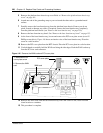
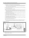
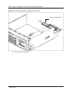
6 Disconnect any connectors from the front of the base function tray.
7 Partially remove the base function tray from the platform base chassis (See “Remove the base
function tray” on page 150). Do not exert force on the DS30 cables and connectors. Ensure
you do not pinch, stretch or damage any cables.
8 Remove the WAN card if applicable (see “Remove the WAN card” on page 219). Continue to
the next step when complete.
9 Disconnect the DS30 cables from the MSC.
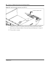
10 Remove the base function tray completely from the platform base chassis. Ensure you do not
pinch, stretch or damage any cables. Refer to “Remove the base function tray” on page 150.
Place the base function tray on a flat, clean and static-free surface. Continue to the next step of
this procedure when complete.
11 Remove the base function tray bezel. See “Remove the base function tray bezel” on page 153.
Continue to the next step when complete.
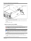
12 Loosen and remove the PCI cover plate screw (use a #2 Phillips screwdriver - see Figure 146).
Place the PCI cover plate screw in a safe location.
13 Remove the PCI cover plate from the base function tray chassis (see Figure 146 on page 220).
Place the PCI cover plate in a safe location.
14 Remove the MSC. Refer to “Remove the media services card (MSC)” on page 225. Continue
to the next step of this procedure when complete.
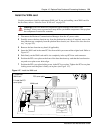
15 Locate the modem card on the main card.
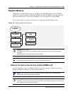
16 Carefully grasp the modem card edges with your finger tips. Carefully pull the modem card
away from the main card. Place the modem card in a clean, safe and static-free location.
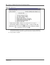
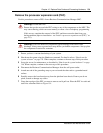
Figure 152 Modem card
17 Carefully grasp the modem card guide pin and remove. Place the pin in a safe location.
18 This procedure is complete.
Base
function
tray face
Modem
card