


Chapter 12 Install Companion or DECT Systems 255
Installation and Maintenance Guide
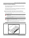
RPI wiring and connections
The maximum two-way DC loop resistance for power pairs, including interconnections for each
base station, is 75 ohms. You need one or two power pairs between the RPI and the base station.
The number of power pairs depends on the wire size of the power pair and the distance between
the base station and the RPI.
The maximum cable distances allowed between the RPI and the base station depend on the size of
wire you use. Refer to Table 27.
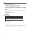
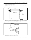
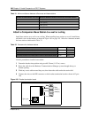
Connect the RPI
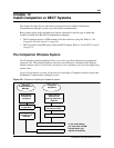
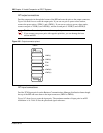
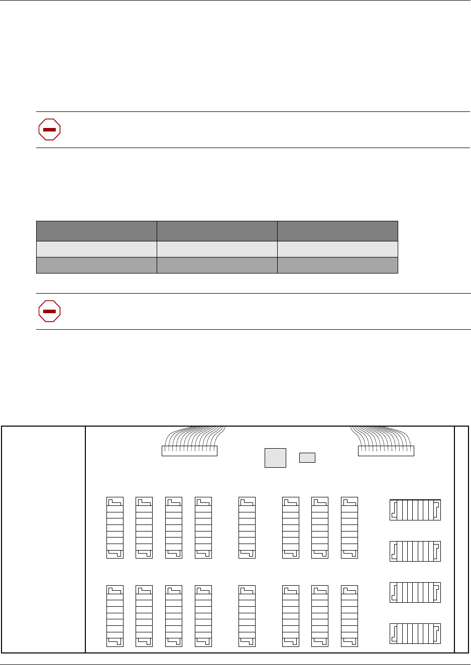
Connect the power pairs to the correct connectors. Figure 165 shows the location of the input and
output connectors on the RPI connector printed-circuit board.
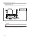
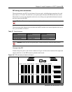
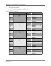
Figure 165 RPI connector printed-circuit board
Caution: Do not run unprotected power cables outdoors.
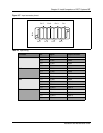
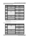
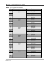
Table 27 Cable distances
Wire size Single pair Double pair
0.6 mm (22 AWG) 800 m (2,500 ft.) 1200 m (4,000 ft.)
0.5 mm (24 AWG) 500 m (1,500 ft.) 1000 m (3,000 ft.)
Caution: When you use two power pairs, connect both pairs with the same polarity.
OBIX1 OBIX2 OBIX3 OBIX4 OBIX9 OBIX10 OBIX11 OBIX12
OBIX5 OBIX6 OBIX7 OBIX8 OBIX13 OBIX14 OBIX15 OBIX16
IBIX1IBIX3IBIX2IBIX4
0B1X1 0B1X2 0B1X3 0B1X4 0B1X9 0B1X10 0B1X11 0B1X12
0B1X5 0B1X6 0B1X7 0B1X8 0B1X9 0B1X13 0B1X14 0B1X15
IBIX4 IBIX3 IBIX2
IBIX2