


74 Chapter 1 Introduction to the Business Communications Manager Platform Hardware
P0993133 03
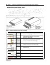
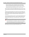
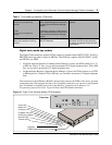
Media bay module DIP switches
The underside of most modules has a set of DIP switches that set the DS30 channel numbers and
offsets used by the module. Figure 39 shows the location of the DIP switches on the module. The
exception to this is the DECT module, where the switches are found on the rear of the module.
Refer to “Digital enhanced cordless telecommunications (DECT) media bay module” on page 81.
For more information about setting DIP switches, refer to Appendix , “Telephony Hardware
Selection and Settings.
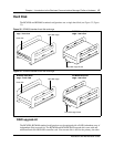
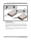
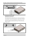
Figure 39 Underside of module showing DIP switches
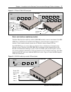
Trunk Media Bay Modules
You install the trunk media bay modules in the base function tray or the Business Communications
Manager expansion unit. The BCM200 holds a maximum of two media bay modules. The
BCM400 holds a maximum of four media bay modules. The expansion unit holds a maximum of
six media bay modules.
Trunk media bay modules connect telecommunications lines to the Business Communications
Manager system.
These are determined by:
• which lines are available from your telephone service provider
• what lines you require for the types of telephones you want to use
• budget considerations
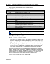
Table 9 lists the types of trunk media bay modules that are available for the Business
Communications Manager system:
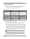
Table 9 Trunk media bay modules
Module type What it does Special notes
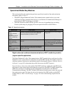
DTM
“Digital trunk media bay module”
Connects digital public switched
telephone lines to the Business
Communications Manager system.
Can connect to four types of lines: TI,
NA PRI, ETSI (in UK only), and Euro
PRI.
Rear of module
DIP switches
Underside of module