


Chapter 10 Replace Data Cards and Processing Hardware 229
Installation and Maintenance Guide
Install the modem card
Use this procedure to install a modem card in a base function tray. This procedure assumes the
base function tray is not installed in the platform base chassis.
1 Obtain a correct and functional modem card.
2 Disconnect the Business Communications Manager from the AC power outlet.
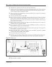
3 Attach one end of the grounding strap to your wrist and the other end to a grounded metal
surface.
4 Install the modem card guide pin.
5 Carefully grasp the new modem card with your finger tips.
6 Install the modem card in the correct location on the main card. Ensure the modem card pins
correctly align with the main card modem connectors and modem guide pin.
7 Gently push on the modem card with your fingertips until it fully seats in the main card
modem connectors.
8 If applicable, connect the RJ11 modem card connector to the main card socket.
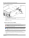
9 Install the MSC in the correct PCI riser card connector. See “Install the media services card
(MSC)” on page 226. When complete, continue to the next step of this procedure.
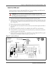
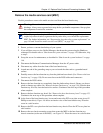
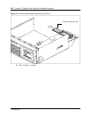
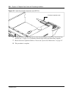
10 Install the two chassis mounting screws that secure the MSC to the base function tray chassis
extension (at the rear of the MSC). See Figure 151.
11 Position the WAN card (if applicable) in the top PCI riser card connector. See “Install the
WAN card” on page 221. When complete, continue to the next step of this procedure.
12 Partially install the base function tray in the platform base chassis.
13 Connect the DS30 connectors to the MSC.
14 Position the PCI cover plate on the front of the base function tray such that the base function
tray and cover plate screw holes align.
15 Position the PCI cover plate locking screw in the PCI cover plate. Tighten the PCI cover plate
locking screw until the plate is firmly set in place (see Figure 147).
16 Push the base function tray completely into the chassis (see “Install the base function tray” on
page 151). Ensure you do not pinch or damage any cables. When complete, continue to the
next step of this procedure.
17 Restore the Business Communications Manager to operation. For details, refer to “Restart the
System after Maintenance” on page 147. When complete, continue to the next step of this
procedure.
18 This procedure is complete.
Warning: Protect the hardware components against damage from electro-static
discharge. Always wear a ground wrist strap before you handle components. Always place
the components in static-free container.