


Chapter 9 Replace or Upgrade a Power Supply 203
Installation and Maintenance Guide
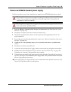
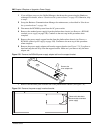
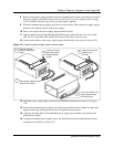
10 Attach the 20 pin motherboard connector and the +12V power connector into the I/O card.
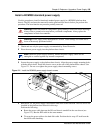
11 Route the power cable, auxilliary and IDE cable to the hard disk cage. Bundle the cables
together and fasten to the roof of the platform base chassis using the cable clamp (see Figure
130).
12 Connect the power cable and IDE cable to the hard disk.
13 Run the auxilliary cable to the chassis cable slot (see next step).
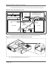
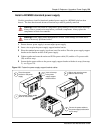
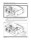
14 Connect cable runs P2 and P3 to the media bay backplane as follows.
a Connect cable P2 into the bottom media bay module backplane power connector
b Connect cable P3 into the top media bay module backplane connector.
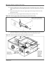
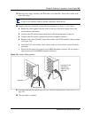
c Bundle power cables P2 and P3 along with auxiliary cable (P7/8) together with a grommet
(see Figure 138).
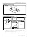
d Insert the P2, P3 and auxiliary cables into the cable slot on the chassis (secured with the
grommet).
15 This procedure is complete.
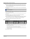
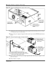
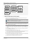
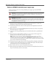
Upgrade to a redundant power supply
Use the procedures in this section to upgrade a BCM400 platform base chassis, currently equipped
with a standard power supply, with a redundant power supply. Figure 131 provides an overview of
the steps required to upgrade your Business Communications Manager (BCM400) system from a
standard power supply to a redundant power supply.
Note: A Business Communications Manager expansion unit with a standard power
supply cannot be upgraded. You must replace the expansion unit chassis.
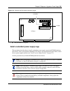
Note: When you install a redundant power supply, you must also install a redundant
cooling fan included with the redundancy upgrade kit.
Note: When you install a redundant power supply, you must also remove the jumper
installed in the PSU Status connector (RPS output signaling connector) on the I/O card.