


198 Chapter 9 Replace or Upgrade a Power Supply
P0993133 03
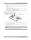
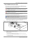
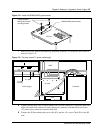
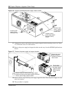
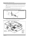
10 Loop the cables together and tie wrap to the side of the power supply to remove P1, P9, P3,
P7/8 excess cable length. Fold the cables to the rear of the platform base chassis and secure
with a tie-wrap. Ensure the cables are tied far enough back so they do not interfere with the
insertion of the base function tray.
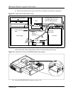
11 Attach the fan plug to the I/O card “Fan #1” connection. Loop excess fan cable length under
the I/O card.
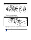
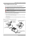
12 Insert the base function tray fully into the platform base chassis. Ensure the base function tray
does not interfer with any cabling.
13 Replace the platform base chassis top cover. See “Install the platform base chassis top cover”
on page 163.
14 Press the power supply switch to the ON position (if applicable). Plug the Business
Communications Manager power cord into an AC power outlet.
15 Restore the Business Communications Manager to operation. For details, refer to “Restart the
System after Maintenance” on page 147. The Business Communications Manager system
starts when you connect the AC power cord. Wait for the start-up process to finish.
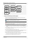
16 Monitor the power LED on the base function tray. Refer to Table 24.
a If the Business Communications Manager does not power-up, press the reset button on the
base function tray front panel.
b If the Power LED is red, and does not respond to a manual reset, this indicates a faulty
power condition. Contact your Nortel Networks representative.
c If the Power LED indicates green, the system is operating normally. Continue to the next
step in this procedure.
17 This procedure is complete.
Note: Verify the power supply cables are connected correctly and do not interfere with
any internal components.
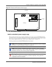
Table 24 Power supply LED
LED
Label
Description
Green
LED On
Green
LED Flash
Red LED On (Only)
Green
LED Off
Indicates state of system power. OK N/A a minimum of 1 PS needs
attention*
N/A