


Chapter 10 Replace Data Cards and Processing Hardware 239
Installation and Maintenance Guide
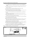
Remove the clock/calendar battery
Use this procedure to remove the clock/calendar battery.
1 If you still have access to the Unified Manager, shut down the system using the Shutdown
command. For details refer to “Shut down the system software” on page 145. Otherwise, skip
to step 2.
2 Set up the server for maintenance, as described in “Shut down the system hardware” on page
146.
3 Disconnect the Business Communications Manager from the AC power outlet.
4 Attach one end of the grounding strap to your wrist and the other end to a grounded metal
surface.
5 Disconnect any connectors from the front of the base function tray.
6 Partially remove the base function tray from the platform base chassis. Do not crimp, stretch
or damage cables or connectors.
7 Remove the base function tray bezel. See “Remove the base function tray bezel” on page 153.
Continue to the next step of this procedure when complete.
8 Remove the WAN card (if applicable). See “Remove the WAN card” on page 219. Continue to
the next step of this procedure when complete.
9 Disconnect the DS30 cables from the MSC. Do not crimp, stretch or damage cables or
connectors.
10 Completely remove the base function tray from the platform base chassis. See “Remove the
base function tray” on page 150. Continue to the next step of this procedure when complete.
11 Remove the media services card (see “Remove the media services card (MSC)” on page 225).
Continue to the next step of this procedure when complete.
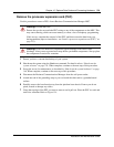
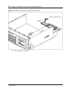
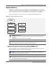
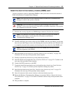
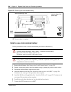
12 Use your finger to carefully lift the battery out of the socket. For the location of the battery
socket, refer to Figure 159.
Warning: Protect the hardware components against damage from electro-static
discharge. Always wear a ground wrist strap before you handle components. Always place
the components in static-free container.
Caution: Do not use any type of tool to remove the battery.