


Chapter 6 Prepare Hardware for Maintenance or Upgrades 161
Installation and Maintenance Guide
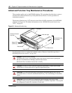
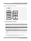
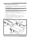
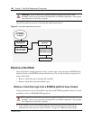
Remove and Install the Platform Base Chassis Top Cover
Use the procedures in this section to either remove or install the top cover of the platform base
chassis. You must remove the top cover to access the cabling or hardware components such as
standard power supply, I/O card or backplanes.
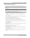
Remove the platform base chassis top cover
Use this procedure to remove the top cover of the BCM200 or BCM400 platform base chassis.
This procedure assumes that you intend to perform maintenance activities. Do not operate the
Business Communications Manager with the top cover removed. Do not leave the top cover
removed for extended periods of time.
1 If you still have access to the Unified Manager, shut down the system using the Shutdown
command. For details refer to “Shut down the system software” on page 145. Otherwise, skip
to step 2.
2 Set up the server for maintenance, as described in “Shut down the system hardware” on page
146.
3 Disconnect the Business Communications Manager from the AC power outlet.
4 If required, remove the platform base chassis from the server rack.
5 Attach one end of the grounding strap to your wrist and the other end to a grounded metal
surface.
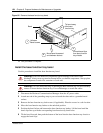
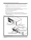
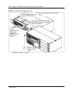
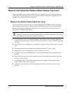
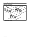
6 Remove the two top cover screws located at the rear of the platform base chassis. Place the
screws in a safe location.
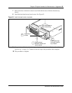
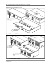
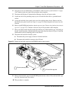
7 Lift the back of the cover and slide rear-ward until it disengages from the platform base
chassis. Refer to Figure 89 or Figure 89.
8 Lift the top cover up and away from the platform base chassis. Place the cover in a safe
location.
Warning: Protect the hardware components against damage from electro-static
discharge. Always wear a ground wriststrap before you handle components. Always place
the components in static-free container or work area.