


Chapter 9 Replace or Upgrade a Power Supply 209
Installation and Maintenance Guide
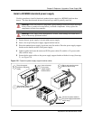
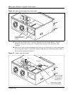
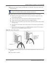
19 Run the power supply, auxilliary and IDE cables to the hard disk. Secure these cables in the
new cable clamp.
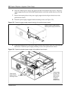
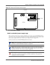
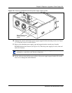
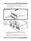
20 Connect cable runs P2 and P3 to the media bay backplane (see Figure 137) as follows:
a Bundle the cables together. Run the cables on the top of the power supply chassis and
secure with the cable clamp.
b Connect cable P2 into the bottom media bay module backplane power connector
c Connect cable P3 into the top media bay module backplane connector.
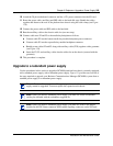
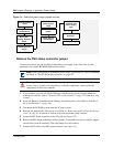
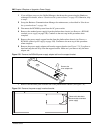
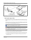
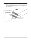
d Bundle power cables P2 and P3 along with auxiliary cable (P7/8) together with a grommet
(see Figure 138).
e Insert the P2, P3 and auxiliary cables into the cable slot on the chassis (secured with the
grommet).
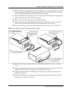
f Ensure that one power run connects to one MBM backplane connector. Do not connect a
single power run to both MBM backplane connectors.
Figure 138 Install a cable grommet
21 Install the platform base chassis top cover. See “Install the platform base chassis top cover” on
page 163.
22 This procedure is complete.
Note: Verify the power supply cables are connected correctly, completely and are routed
so they do not interfere with any internal components when moved.
Cable grommet
Insert the P2, P3
and auxiliary
cables into the
cable slot
Cable slot