


Chapter 9 Replace or Upgrade a Power Supply 205
Installation and Maintenance Guide
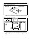
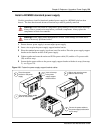
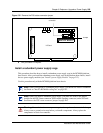
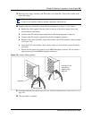
Figure 132 Remove the PSU status connector jumper
8 This procedure is complete.
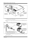
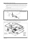
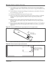
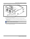
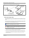
Install a redundant power supply cage
This procedure describes how to install a redundant power supply cage in the BCM400 platform
base chassis. After you install the redundant power supply cage in the platform base chassis, install
the two power supply modules (see “Install a power supply module” on page 212).
Use this procedure only with the BCM400 platform base chassis.
Note: When you upgrade to a redundant power supply, you should also install a redundant
fan. Refer to “Install a BCM400 cooling fan” on page 182.
Note: When you install a redundant power supply, you must also remove the jumper
installed in the PSU Status connector (RPS output signaling connector) on the I/O card.
See Remove the PSU status connector jumper on page 204.
Warning: Protect the hardware components against damage from electrostatic discharge.
Always wear a ground wrist strap before you handle components. Always place the
components in static-free container.
I/O Card
PSU Status
connector
Jumper