


Chapter 8 Install or Replace a Cooling Fan 183
Installation and Maintenance Guide
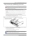
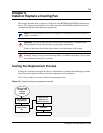
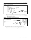
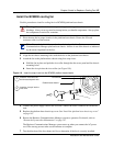
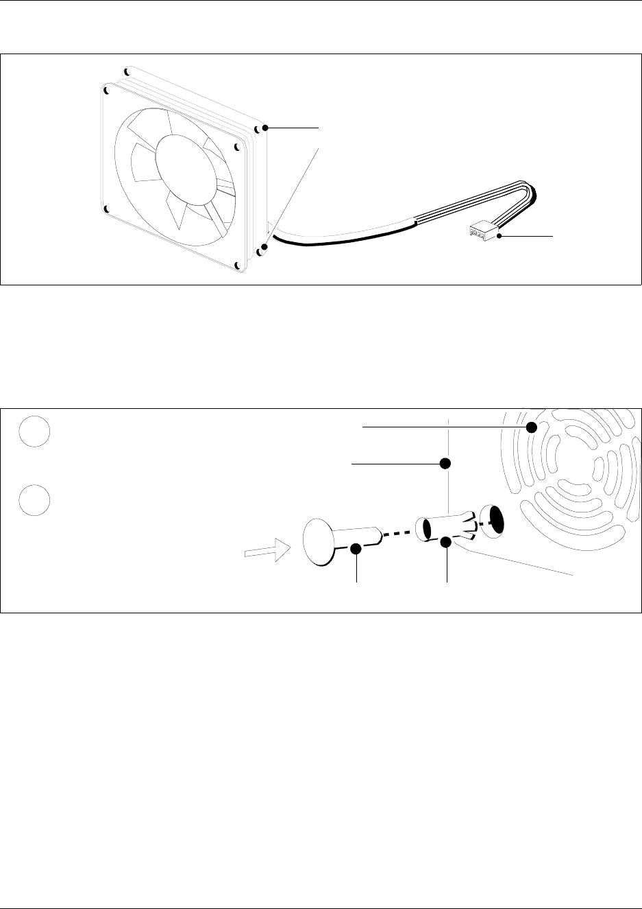
Figure 108 Fan chassis mounting holes
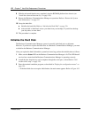
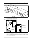
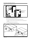
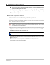
b Hold the fan in place against the fan access panel. Push the rivet collar through the fan
access panel and fan chassis mounting holes.
c Insert the rivet pin into the rivet collar. Repeat this step for the second fan in the BCM400
RFO configuration (see Figure 109).
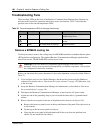
Figure 109 Insert the snap rivets into the BCM400 fan access panel
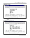
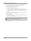
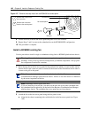
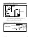
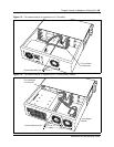
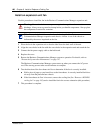
3 Connect the power supply cables for each fan to the I/O card (see Figure 110):
a Connect Fan #1 (fan farthest from the power supply) to connector #1 on the I/O card.
b Connect Fan #2 (fan closest to the power supply) to connector #2 on the I/O card.
Chassis mounting
holes
I/O card fan
connector
fan access panel
Rivet pin
Rivet collar
Insert the rivet collar into
the fan access panel hole.
Insert the rivet pin into the
rivet collar.
Fan exhaust
1
2