


134 Chapter 5 Business Communications Manager System Startup
P0993133 03
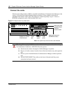
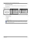
Connect wiring to the modem
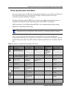
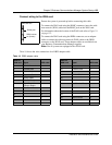
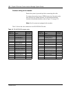
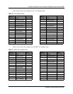
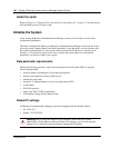
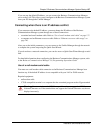
Table 19 shows the wire connections for a RS-422/EIA 530 cable
Ensure the system is powered up before connecting this cable.
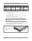
To connect the modem, insert a PSTN line into the Line jack on the
base function tray modem interface. For information about the
location of the modem interface, refer to Figure 74 on page 132.
Note: Not all systems are equipped with a modem.
Table 19 RS-422/EIA 530 adapter cable
DB26 on
WAN card
Signal
RS-422/EIA
530 cable
DB26 on
WAN card
Signal
RS-422/EIA
530 cable
1 Protective Ground 1 14 Transmit Data B 14
2 Transmit Data A 2 15 Transmit Clock A 15
3 Receive Data A 3 16 Receive Data B 16
4 Request to Send A 4 17 Receive Clock A 17
5 Clear to Send A 5 18 18
6 Data Set Ready A 6 19 Request To Send B 19
7 Signal Ground 7 20 Data Terminal Ready A 20
8 Data Carrier Detect A 8 21 21
9 Receive Clock B 9 22 Data Set Ready B 22
10 Data Carrier Detect B 10 23 Data Terminal Ready B 23
11 External Clock B 11 24 External Clock A 24
12 Transmit Clock B 12 25 25
13 Clear To Send B 13 26