


156 Chapter 6 Prepare Hardware for Maintenance or Upgrades
P0993133 03
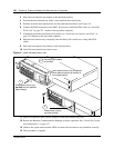
Advanced Function Tray Maintenance Procedures
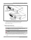
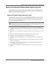
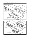
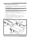
This procedure applies only to the BCM400 platform. This procedure describes how to remove
and install the advanced function tray in the platform base chassis. Use this procedure for
maintenance purposes.
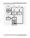
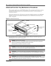
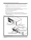
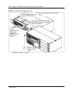
The advanced function tray (AFT) houses the hard disk or RAID components for the BCM400
platform (see Figure 84). For further information see also “BCM400 advanced function tray
(AFT)” on page 50.
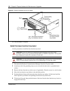
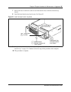
Figure 84 Advanced function tray
For information on how to replace the hard disk, refer to “Remove a hard disk cage from a
BCM400 platform base chassis” on page 168.
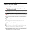
Danger: Electrical shock warning.
Disconnect the power cord, telephone cables and network cables before opening the
Business Communications Manager platform base chassis.
Read and follow installation instructions carefully.
Caution: Use only a Nortel Networks approved replacement. Contact your account
representative for the current list of approved replacement parts.
Warning: Use care when removing or inserting the advanced function tray. Do not
forcefully remove or insert the advanced function tray. You could damage or stretch the
cables.
Warning: Protect the hardware components against damage from electro-static
discharge. Always wear a ground wriststrap before you handle components. Always place
the components in static-free container or work area.
Advanced function
tray chassis
Status LEDs
(RAID only)
Reset button
Reserved bay
Advanced function
tray latch
Hard disk
Bezel screw
Hard disk cage