


Chapter 10 Replace Data Cards and Processing Hardware 241
Installation and Maintenance Guide
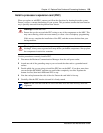
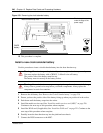
8 Position the PCI cover plate on the front of the base function tray such that the base function
tray and cover plate screw holes align.
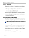
9 Position the PCI cover plate locking screw in the PCI cover plate. Tighten the PCI cover plate
locking screw until the plate is firmly set in place (see Figure 147).
10 Install the base function tray bezel (see “Install the base function tray bezel” on page 154).
Continue to the next step in this procedure when complete.
11 Completely insert the base function tray into the platform base chassis. See “Install the base
function tray” on page 151. Continue to the next step of this procedure when complete.
12 Restore the Business Communications Manager to operation. For details, refer to “Restart the
System after Maintenance” on page 147. Continue to the next step of this procedure when
complete.
13 This procedure is complete.