


Chapter 6 Prepare Hardware for Maintenance or Upgrades 157
Installation and Maintenance Guide
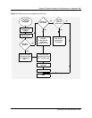
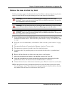
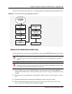
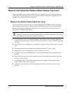
Use the flow chart shown in Figure 85 as a summary guide to maintain the advanced function tray.
Figure 85 Advanced function tray replacement overview
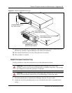
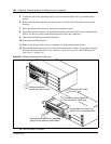
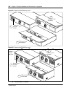
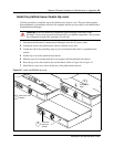
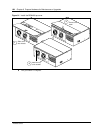
Remove the advanced function tray
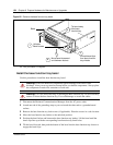
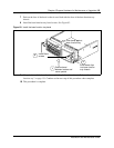
Use this procedure to remove the advanced function tray from the BCM400 platform base chassis.
1 If you still have access to the Unified Manager, shut down the system using the Shutdown
command. For details refer to “Shut down the system software” on page 145. Otherwise, skip
to step 2.
2 Set up the server for maintenance, as described in “Shut down the system hardware” on page
146.
3 Disconnect the Business Communications Manager from the AC power outlet.
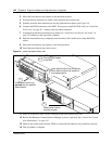
4 Remove the platform base chassis top cover (see “Remove the platform base chassis top
cover” on page 161). Return to this step when complete.
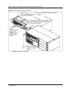
Warning: Use care when removing or inserting the advanced function tray. Do not
forcefully remove or insert the advanced function tray. You could damage or stretch the
cables.
Warning: Protect the hardware components against damage from electro-static
discharge. Always wear a ground wriststrap before you handle components. Always place
the components in static-free container or work area.
If possible,
do a software
shutdown
Perform BCM
maintenance
setup
Remove the
advanced function
tray
Remove hard
disk.
Install new hard
disk in
replacement AFT
Insert the
advanced function
tray
Restore unit to
operation
Check LEDs
END