


66 Chapter 1 Introduction to the Business Communications Manager Platform Hardware
P0993133 03
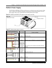
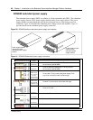
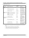
BCM400 redundant power supply
The redundant power supply (RPS) is available as a field replaceable unit (FRU). The redundant
power supply consists of two power supply modules and a power supply chassis. The power
supply modules are interchangeable and can be exchanged one at a time during power-on
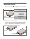
conditions. Figure 30 illustrates the redundant power supply chassis and modules. Figure 31
provides details on the redundant power supply connectors.
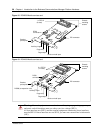
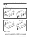
Figure 30 BCM400 platform redundant power supply and modules
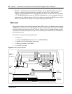
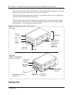
Figure 31 BCM400 Redundant power supply connectors
Power supply module
removed from the
redundant power supply
chassis
Power supply module
inserted in the
redundant power
supply chassis
Connector Configuration for
Redundant Sparkle Power Supply
Cable Lengths and
Markings
550mm (P2)
550mm (P3)
325mm to first
(P4), +50mm to
next (P5),
+100mm to last
(P6) (total 475mm)
340mm to first
(P7)(right angle)
,
+150mm to next
(P8) (total 490mm
)
515mm (P1)
515mm (P9)
515mm (PA)
300mm (PB)
Route to Media bay backplane 1: Tie any slack at
the connector (behind MBM)
Route to Media bay backplane 2: Tie any slack at
the connector (behind MBM)
To hard disk: Tie any slack at the power supply. Tuck
any loose connectors under hard disk cage.
Unused. Tie to the center of the hard disk cage.
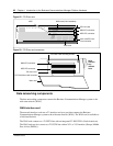
Route to I/O card.
Route to I/O card.
Route to I/O card.
Unused
Purpose and Notes