


44 Chapter 1 Introduction to the Business Communications Manager Platform Hardware
P0993133 03
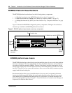
BCM200 Platform Base Hardware
The BCM200 platform base hardware has the following primary components:
• 1 x Platform base chassis (see “BCM200 platform base chassis” on page 44)
• 2 x Media bay module bays (MBM) (see “Media bay modules (MBMs)” on page 71)
• 1 x Sliding base function tray (BFT) (see “Base Function Tray Component Hardware” on page
54)
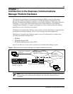
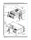
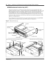
Figure 3 illustrates the BCM200 configuration primary components. The figure shows the base
function tray installed in the BCM200 platform base chassis.
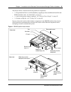
Figure 3 BCM200 platform base chassis and primary components
BCM200 platform base chassis
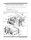
The BCM200 platform base chassis design provides multiple points of access to the base platform
hardware components. The front of the chassis has three assemblies that house one base function
tray and two media bay modules (MBMs). The rear of the chassis provides mount points for the
fan and power supply. The rear of the chassis also has a removeable panel to provide access to the
hard disk. The top cover has a removable section to allow access to the cables, connectors, power
supply, hard disk and cooling fan.
Rack mount brackets allow you to install the chassis in a server rack. An optional wall mount
bracket is avialable separately. Rubber feet attach under the platform base chassis if you want to
place the Business Communications Manager unit on a flat surface. For further information on
chassis bracket installation, refer to Chapter 3, “Install the Business Communications Manager &
Expansion Unit Platform Base Chassis’.
Base function
tray latch
Platform
base
chassis
MBM
ejector
2 x Media bay module (MBM) bay
s
Base function tray