


Telephony Hardware Selection and Settings 327
Installation and Maintenance Guide
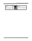
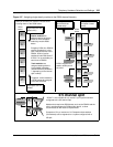
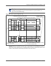
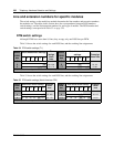
Figure 199 How to use the configuration map
Example: Position your DSM 32 module (step 1), which requires two full DS30 buses (step 2), in
DS30 2 and 3 (step 3). Moving across, note that the offset is 0 (step 4). Set the DIP switches on the
module to match the DIP switch settings indicated for that offset (step 5).
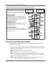
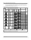
Note: If you must assign specific line or extension numbers to a module, refer to the
individual switch tables in “Line and extension numbers for specific modules” on
page 332 for line and DN listings.
DS30
bus #
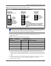
Media bay module positioning DIP switch setting
Off-set
4x16 ASM
8
DTM CTM
CTM 8 BRI
123
(offset)
456
(DS30 ch)
2 on on on on on on
0
7 on on on off on off 0
on on off off on off 1
on off on off on off 2
on off off off on off 3
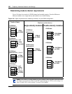
1. Indicate the modules you want to install
2. Note how many DS30 buses each module requires
3. Choose the DS30 numbers to
assign to the modules
4. Assign an offset
number to each module
5. Make a note of the DIP switch settings for the DS30/offset numbers
1
2
3
4
5
5
DIP switch setting for offset
2
3
4