


Chapter 1 Introduction to the Business Communications Manager Platform Hardware 61
Installation and Maintenance Guide
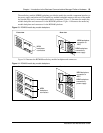
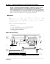
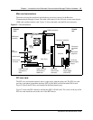
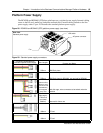
Main card connections
The main card provides peripheral and telephony processing control for the Business
Communications Manager system. The main card connects to the I/O card, system status display
(SSD) card, modem interface card. Figure 21 shows the main card and I/O card connectors.
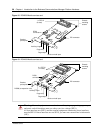
Figure 21 Card connections
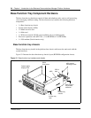
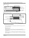
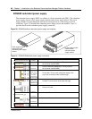
PCI riser card
The PCI riser card extends upward, and at a right angle, from the main card. The PCI riser card
provides a peripheral component interface (PCI) for the MSC and field installed WAN cards.
Figure 22 shows the PCI riser card installed in the Base function tray.
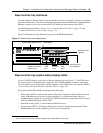
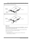
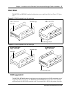
Figure 23 shows the PCI connectors without the MSC or WAN cards. Two screws at the top of the
PCI riser card attach the card to the side of the BFT chassis.
Connect to hard disk
I/O Card
Main Card
Connect to
single fan
Connect to
redundant
fan
Connect to
Power supply
(20 pin)
Connect to
Power supply
(PSU AUX)
Upper PCI riser
connection to
WAN card
Lower PCI riser
connection to
MSC
Modem card
connector
SSD board
connector
Main card
and I/O card
connector
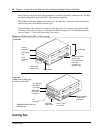
SSD
connector
DIMM connectors
Modem card
Chassis
front
Chassis
rear