


152 Chapter 6 Prepare Hardware for Maintenance or Upgrades
P0993133 03
3 Move the base function tray latches to the unlocked position.
4 Position the base function tray in the correct platform base chassis bay.
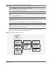
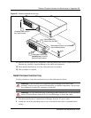
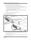
5 Partially insert the base function tray into the platform base chassis (see Figure 81).
6 Connect the DS30 connectors to the MSC. If necessary, install the WAN card (see “Install the
WAN card” on page 221 - return to this step when complete).
7 If required, install the base function tray bezel (see “Install the base function tray bezel” on
page 154). Return to this step when complete.
8 Push the base function tray completely into the chassis. Be careful not to crimp the DS30
cables.
9 Move the base function tray latches to the locked position.
10 Install the base function tray latch screws.
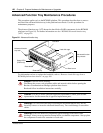
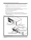
Figure 81 Install the base function tray
11 Insert all connectors in the correct locations on the base function tray face.
12 Restore the Business Communications Manager system to operation. See: “Restart the System
after Maintenance” on page 147.
13 Observe the system status monitor LEDs to ensure the base function tray initializes correctly.
14 This procedure is complete.
Fasten base function
tray latch screws
4
Slide base function tray
partially into the platform
base chassis
1
3
2
Connect DS30 cables
to the MSC
Insert base function tray completely.
Move base function tray latches to
the locked position