


326 Telephony Hardware Selection and Settings
P0993133 03
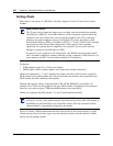
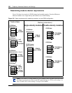
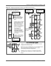
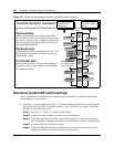
Figure 198 Assigning double density modules to the DS30 channel hierarchy
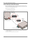
Determine module DIP switch settings
After you determine in which order you want to assign the modules, you determine the specific
switch settings for each module.
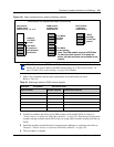
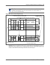
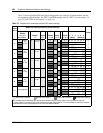
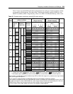
1 Use Table 52 (trunk modules) and Table 53 (station modules) to determine a switch setting for
all modules except the DECT and FEM modules. Figure 199 shows an example of the table
and how to do the following steps:
Step 1: On Table 52 or Table 53 circle the module names.
Step 2: Number the order in which you want to assign the modules.
Step 3: Determine the number of DS30s each module requires. For some station modules
this will depend on whether you choose to set the module to single or double density.
Step 4: Circle the DS30 bus and offset numbers.
Step 5: Follow the DS30 bus and offset number to the far right column where the switch
settings are indicated. Circle the setting for each module.
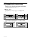
Partial density
Systems configured with Partial double density (PDD),
allow Companion telephones on DS30 6 and 7 (if the sys-
tem is set to a 2/6 split). In this configuration, DS30 6 and 7
only allow single-density modules. DS30 2 to 5 are set to
allow double density modules.
Double density
Systems configured with Full double density (FDD), do not
allow Companion telephones. All DS30s are set to allow
double density modules.
3/5 channel split
Works in same as shown in the single-density diagram. If
the system is set to a 3/5 split, DS30 7 is not available to
any media bay modules.
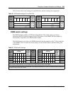
DS30
buses
4X16
DD DSM 32+
Example of
North American-
based setup
Example of a
European- based
setup
DD DSM 32+
DS30 5 supports
the station module
part of the 4X16
BRI
SD DSM 32
Companion
BRI
DECT
DD DSM 32+
DD DSM 32+
Double-density example
(system configured as Partial Density)
DD DSM 16+
DD DSM 16+
CTM
CTM
CTM