


190-00498-07 Rev. A
Garmin G1000 Pilot’s Guide for Cessna Nav III
81
ENGINE INDICATION SYSTEM
SYSTEM
OVERVIEW
FLIGHT
INSTRUMENTS
EIS
AUDIO PANEL
& CNS
FLIGHT
MANAGEMENT
HAZARD
AVOIDANCE
AFCS
ADDITIONAL
FEATURES
APPENDICES INDEX
SECTION 3 ENGINE INDICATION SYSTEM (EIS)
NOTE: Refer to the Pilot’s Operating Handbook (POH) for limitations.
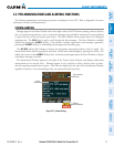
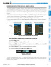
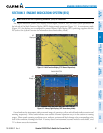
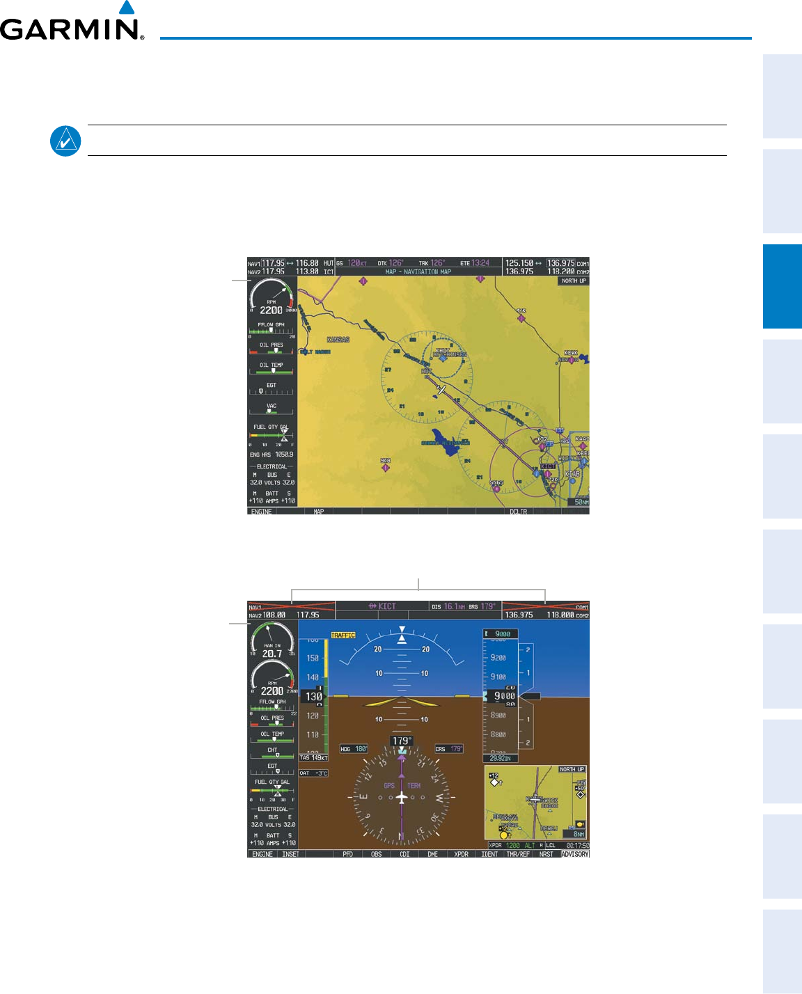
The Engine Indication System (EIS) displays critical engine, electrical, fuel, and other system parameters on
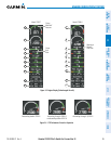
the left side of the Multi Function Display (MFD) during normal operations (Figure 3-1). In reversionary mode
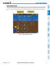
(Figure 3-2), the displays are re-configured to present Primary Flight Display (PFD) symbology together with the
EIS (refer to the System Overview for information about Reversionary Mode).
EIS
Display
Figure 3-1 Multi Function Display (172S Normal Operations)
Failed NAV/COM
EIS
Display
Figure 3-2 Primary Flight Display (182T Reversionary Mode)
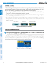
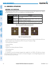
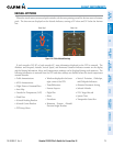
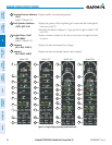
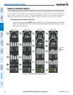
Green bands on the instruments indicate normal ranges of operation; yellow and red bands indicate caution and
warning, respectively. White bands indicate areas outside of normal operation not yet in the caution or warning
ranges. When unsafe operating conditions occur, readouts, pointers and labels change color corresponding to the
level of the condition; warnings also flash. If sensory data to an instrument becomes invalid or unavailable, a red
“X” is shown across the instrument.