


190-00498-07 Rev A
Garmin G1000 Pilot’s Guide for Cessna Nav III
491
ADDITIONAL FEATURES
SYSTEM
OVERVIEW
FLIGHT
INSTRUMENTS
EIS
AUDIO PANEL
& CNS
FLIGHT
MANAGEMENT
HAZARD
AVOIDANCE
AFCS
ADDITIONAL
FEATURES
APPENDICES INDEX
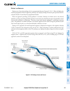
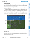
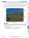
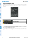
Obstacles are represented on the synthetic terrain display by standard two-dimensional tower symbols found
ontheInsetmapandMFDmapsandcharts.Obstaclesymbolsappearintheperspectiveviewwithrelative
height above terrain and distancefrom the aircraft. Unlike the Inset map andMFDmovingmapdisplay,
obstacles on the synthetic terrain display do not change colors to warn of potential conflict with the aircraft’s
flight path until the obstacle is associated with an actual FLTA alert. Obstacles greater than 1000 feet below the
aircraft altitude are not shown. Obstacles are shown behind the airspeed and altitude displays.
Figure 8-11 Obstacle
Potential
Impact
Point
Obstacle
Warning
TERRAIN
Annunciation
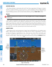
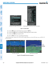
FIELD OF VIEW
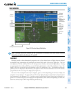
ThePFDeldofviewcanberepresentedontheMFDNavigationMapPage.Twodashedlinesforminga
V-shape in front of the aircraft symbol on the map, represent the forward viewing area shown on the PFD.
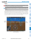
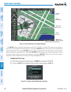
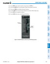
Configuring field of view:
1) While viewing the Navigation Map Page, press the MENU Key to display the PAGE MENU.
2) Turn the large
FMS
Knob to highlight Map Setup and press the
ENT
Key.