


190-00498-07 Rev. A
Garmin G1000 Pilot’s Guide for Cessna Nav III
14
SYSTEM OVERVIEW
SYSTEM
OVERVIEW
FLIGHT
INSTRUMENTS
EIS
AUDIO PANEL
& CNS
FLIGHT
MANAGEMENT
HAZARD
AVOIDANCE
AFCS
ADDITIONAL
FEATURES
APPENDICESINDEX
1.6 SYSTEM OPERATION
NOTE:
In normal operating mode, backlighting can only be adjusted from the PFD. In reversionary mode, it
can be adjusted from the remaining display.
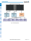
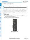
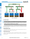
The displays are connected together via a single Ethernet bus for high-speed communication.
Each IAU is
connected to a single display, as shown in Figure 1-1. This allows the units to share information, enabling true system
integration.
. This section discusses normal and reversionary G1000 display operation, as well as the various AHRS
modes and G1000 System Annunciations.
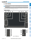
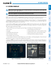
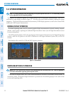
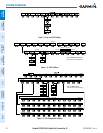
NORMAL DISPLAY OPERATION
In normal operating mode, the PFD presents graphical flight instrumentation (attitude, heading, airspeed,
altitude, vertical speed), replacing the traditional flight instrument cluster (see the Flight Instruments Section
for more information).
The MFD normally displays a full-color moving map with navigation information (see the Flight Management
Section), while the left portion of the MFD is dedicated to the Engine Indication System (EIS; see the EIS
Section).
Both displays offer control for COM and NAV frequency selection.
Figure 1-9 Normal Mode
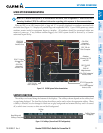
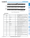
REVERSIONARY DISPLAY OPERATION
NOTE: The G1000 System alerts the pilot when backup paths are utilized by the LRUs. Refer to Appendix A
for further information regarding system-specific alerts.
In the event of a display failure, the G1000 System automatically switches to reversionary (backup) mode. In
reversionary mode, all important flight information is presented on the remaining display in the same format
as in normal operating mode.