


190-00498-07 Rev. A
Garmin G1000 Pilot’s Guide for Cessna Nav III
39
SYSTEM OVERVIEW
SYSTEM
OVERVIEW
FLIGHT
INSTRUMENTS
EIS
AUDIO PANEL
& CNS
FLIGHT
MANAGEMENT
HAZARD
AVOIDANCE
AFCS
ADDITIONAL
FEATURES
APPENDICES INDEX
gPs cDi
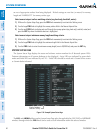
The GPS CDI Box on the System Setup Page allows the pilot to define the range for the on-screen course
deviation indicator (CDI). The range values represent full range deflection for the CDI to either side. The
default setting is ‘AUTO’. At this setting, leaving the departure airport the CDI range is set to 1.0 nm and
gradually ramps up to 2 nm beyond 30 nm from the departure airport. The CDI range is set to 2.0 nautical
miles during the en route phase of flight. Within 30 nm of the destination airport, the CDI range gradually
ramps down to 1.0 nm (terminal area). During approach operations, the CDI range ramps down even
further to 0.3 nm. This transition normally occurs within 2.0 nm of the final approach fix (FAF).
If a lower CDI range setting is selected (i.e., 1.0 or 0.3 nm), the higher range settings are not selected
during any phase of flight. For example, if 1.0 nm is selected, the system uses this for en route and terminal
phases and ramps down to 0.3 nm during an approach. Note that the Receiver Autonomous Integrity
Monitoring (RAIM) protection limits follow the selected CDI range and corresponding flight phases.
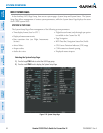
The GPS CDI Box on the System Setup Page displays the following:
•SelectedCDIrange(auto,2nm,1nm,0.3nm)
•CurrentsystemCDIrange(2nm,1nm,0.3nm)
Changing the CDI range:
1) While on the System Setup Page, press the FMS Knob momentarily to activate the flashing cursor.
2) Turn the large FMS Knob to highlight the selected eld in the GPS CDI Box.
3) Turn the small FMS Knob to display and scroll through the range list and press the ENT Key when the desired
selection is highlighted.
4) Press the FMS Knob to deactivate the cursor.
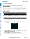
cOm cOnFigURatiOn
NOTE
: 8.33 kHz VHF communication frequency channel spacing is not approved for use in the United States.
Select the 25.0 kHz channel spacing option for use in the United States.
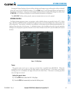
The COM Configuration Box on the System Setup Page allows the pilot to select 8.33 kHz or 25.0 kHz
COM frequency channel spacing.
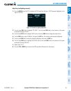
Change COM channel spacing:
1) While on the System Setup Page, press the FMS Knob momentarily to activate the flashing cursor.
2) Turn the large FMS Knob to highlight the channel spacing eld in the COM Conguration Box.
3) Turn the small FMS Knob to select the desired spacing and press the ENT Key.
neaRest aiRPORts
The Nearest Airports Box on the System Setup Page defines the minimum runway length and surface type
used when determining the nine nearest airports to display on the MFD Nearest Airports Page. A minimum
runway length and/or surface type can be entered to prevent airports with small runways or runways that