


62
CHAPTER 3 CPU
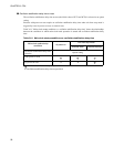
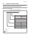
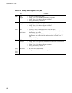
Table 3.7-2 Standby control register (STBC) bits
Bit Function
Bit 7 STP:
Stop bit
• Sets the CPU entering stop mode.
• Writing "1" to this bit sets the CPU entering stop mode.
• Writing "0" to this bit has no effect on operation.
• Reading this bit always returns "0".
Bit 6 SLP:
Sleep bit
• Sets the CPU entering sleep mode.
• Writing "1" to this bit sets the CPU entering sleep mode.
• Writing "0" to this bit has no effect on operation.
• Reading this bit always returns "0".
Bit 5 SPL:
Pin state
specification
bit
• Specifies the states of the external pins during stop mode.
• Writing "0" to this bit specifies that external pins hold their states (levels)
when entering stop mode.
• Writing "1" to this bit specifies that external pins go to high-impedance state
when entering stop mode (pin with a pull-up resistor (optional) go to "H"
level).
• Initialized to "0" by a reset.
Bit 4 RST:
Software
reset bit
• Specifies a software reset.
• Writing "0" to this bit generates an internal reset source for four instruction
cycles.
• Writing "1" to this bit has no effect on operation.
• Reading this bit always returns "1".
Bit 3
Bit 2
Bit 1
Bit 0
Unused bits • The read value is indeterminate.
• Writing to these bits has no effect on operation.