


54
CHAPTER 3 CPU
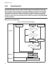
●
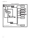
Clock controller
This circuit controls the supply of operating clocks to the CPU and peripheral circuits, selecting the clock
based on the active mode: normal (RUN), or standby (sleep/stop) mode.
Supply of the clock to the CPU is stopped until the clock supply stop signal in the oscillation stabilization
delay time selector is released.
●
Oscillation stabilization delay time selector
This selector selects a delay time between two main clock oscillation stabilization times timed by the
timebase timer as the duration of CPU clock stop signal.
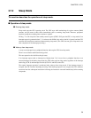
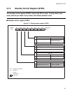
●
STBC register
This register controls from normal operation (RUN) to the standby mode, sets the pin states in the stop
mode, and initiates software reset.
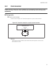
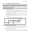
■ Instruction cycle (t
inst
)
Instruction cycle (minimum execution time) is 1/4 of the main clock.