


128
CHAPTER 7 8-BIT PWM TIMER
7.3.1 PWM Control Register (CNTR)
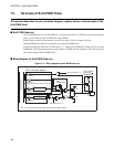
The PWM control register (CNTR) is used to select the operating mode of the 8-bit PWM
timer (interval timer operation or PWM timer operation), enable or disable operation,
select the count clock, control interrupts, and check the state of the 8-bit PWM timer.
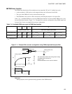
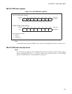
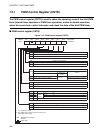
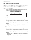
■ PWM control register (CNTR)
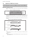
Figure 7.3-3 PWM control register (CNTR)
Address Bit 7 Bit 6 Bit 5 Bit 4 Bit 3 Bit 2 Bit 1 Bit 0 Initial value
0012
H
P/T P1 P0 TPE TIR OE TIE 0-000000
B
R/W R/W R/W R/W R/W R/W R/W
TIE Interrup t request enable bit
0 Disables interrupt request output.
1 Enables interrupt request output.
OE Output pin control bit
0 Functions as a general-purpose port (P41).
1 Functions as the interval timer/PWM timer output pin (PWM).
TIR
Interrupt request flag bit
Read
Write
Interval timer function
PWM timer
function
0
Counter value and set value do not match.
No change
Clears this bit.
1
Counter value and set value match. No effect. The bit does not change.
TPE
Counter operation enable bit
Operating mode selection bit
Clock selection bits
0 Stops count operation.
1 Starts count operation.
P1 P0
0 0
Internal
count
clock
1 t
inst
(*
1
)
0 1 16 t
inst
1 0 64 t
inst
1 1 PWC timer output
P/T
0 Operates as an interval timer.
1 Operates as a PWM timer.
*1: t
inst
: Instruction cycle
*2: The "PWC timer output" referred to here is the
PWC timer output cycle
R/W : Readable and writable
: Unused
: Initial value
(*
1
)
(*
1
)
(*
2
)