238
CHAPTER 12 LCD CONTROLLER/DRIVER
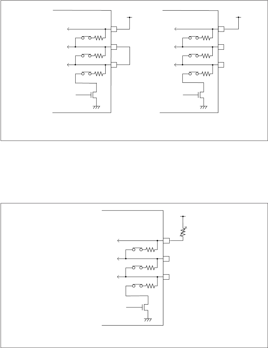
■ Use of internal voltage divider
Figure 12.2-3 "Use of internal voltage divider" shows the voltage divider circuits for 1/2 and 1/3 bias. As
shown in this figure, in the 1/2 bias mode (with LCD enabled) V2 and V1 will be 1/2 of V3 (V3 is the LCD
operating voltage, which is V
CC
in this configuration). In the 1/3 bias mode, V1 is 1/3 of V3, and V2 is 2/3
of V3.
Figure 12.2-3 Use of internal voltage divider
■ Display brightness adjustment when internal voltage divider is used
When internal voltage divider does not provide sufficient LCD display brightness, connect an external
brightness adjust variable resistor between V
CC
and V3 as shown in Figure 12.2-4 "Use of internal voltage
divider with brightness adjustment".
Figure 12.2-4 Use of internal voltage divider with brightness adjustment
V3
R
V
2
R
V1
R
V3
V2
V1
N-ch
V3
R
V
2
R
V1
R
V2
V1
N-ch
LCD enable
LCD enable
MB89950/950A series MB89950/950A series
1/2 bias 1/3 bias
V
1 to V
3: Voltages at V1 to V3 pins.
V3
Vcc
Vcc
V
3
R
V
2
R
V
1
R
V3
V2
V1
N-ch
VR
V
1
to V
3
: Voltages at V1 to V3 pins.
MB89950/950A series
When display brightness adjustment is desired
LCD enable
Vcc


