36
CHAPTER 3 CPU
3.4.1 Interrupt Level Setting Registers (ILR1, ILR2, ILR3)
The interrupt level setting registers (ILR1, ILR2, ILR3) together contain 12 blocks of 2-bit
data, with each data corresponding to an interrupt request from a peripheral function.
The interrupt level for each interrupt is set in that interrupt’s corresponding 2-bit data
(interrupt level setting bits).
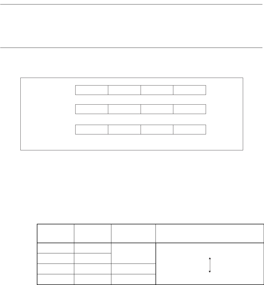
■ Structure of interrupt level setting registers (ILR1, ILR2, ILR3)
Figure 3.4-1 Structure of interrupt level setting registers
Two bits of the interrupt level setting registers are allocated to each interrupt request. The value of the
interrupt level setting bits in these registers sets the interrupt priority (interrupt levels 1 to 3).
The interrupt level setting bits are compared with the interrupt level bits in the condition code register
(CCR: IL1, IL0).
The CPU does not accept interrupt requests set to interrupt level 3.
Table 3.4-2 "Interrupt level setting bit and interrupt level" shows the relationship between the interrupt
level setting bits and the interrupt levels.
Reference:
The interrupt level bits in the condition code register (CCR: IL1, IL0) are normally "11
B
" during main
program execution.
Note:
As the IRL1, ILR2, and ILR3 registers are write-only, the bit manipulation instructions cannot be used.
Register Address Bit 7 Bit 6 Bit 5 Bit 4 Bit 3 Bit 2 Bit 1 Bit 0 Initial value
ILR1 007C
H
L31 L30 L21 L20 L11 L10
L01
L00 11111111
B
WWWWWWWW
WWWWWWWW
WWWWWWWW
ILR2 007D
H
L71 L70
L61
L60 L51 L50 L41 L40 11111111
B
ILR3 007EH
LB1 LB0 LA1 LA0 L91
L90
L81 L80 11111111
B
W: Write-only
Table 3.4-2 Interrupt level setting bit and interrupt level
L01 to LB1 L00 to LB0
Interrupt
request level
Priority
00
1
01
10 2
11 3
High
Low (no interrupt)


