


162
CHAPTER 8 PULSE WIDTH COUNT TIMER (PWC)
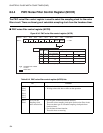
8.7 Operation of Noise Filter Circuit
This section describes the operations of noise filter circuit function when the pulse
width measurement function is selected.
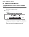
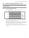
■ Operation of noise filter circuit function
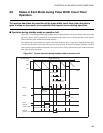
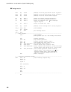
Figure 8.7-1 "Noise filter circuit function settings" shows the settings required to operate as the noise filter
circuit function.
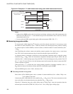
Figure 8.7-1 Noise filter circuit function settings
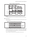
When pulse width measurement function is selected, the noise filter circuit can be used to clear the noise.
By the selecting different value for sampling clock pulse selection bit (NCS1 and NCS0) of noise filter
control register (NCCR), different kind of the noise can be filtered out. Integrating the sampled signal
clears the noise. The maximum width of the cleared noise is as follows:
N
W
= sampling clock cycle x 5
When noise clearing is prohibited, the PWC input is input directly to PWC counter/timer.
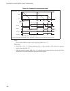
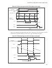
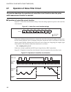
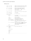
Figure 8.7-2 "Operation of noise filter circuit function" shows the operation of the noise filter circuit.
Figure 8.7-2 Operation of noise filter circuit function
NCCR NCS1 NCS0
: Used bit
: Unused bit
Bit 7 Bit 6 Bit 5 Bit 4 Bit 3 Bit 2 Bit 1 Bit 0
PWC input
Integrated
Sampling
Internal
clock
pulse
value
signal