


150
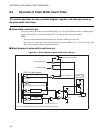
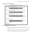
CHAPTER 8 PULSE WIDTH COUNT TIMER (PWC)
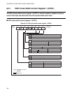
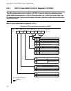
8.3.2 PWC Pulse Width Control Register 2 (PCR2)
The PWC pulse width control register 2 (PCR2) is used to select the operating mode
(pulse width measurement or interval timer operation, etc.), select the count clock, set
the measured pulse (measurement edges), and check the timer output state of the pulse
width count timer.
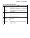
■ PWC pulse width control register 2 (PCR2)
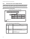
Figure 8.3-4 PWC pulse width control register 2 (PCR2)
Address Bit 7 Bit 6 Bit 5 Bit 4 Bit 3 Bit 2 Bit 1 Bit 0 Initial value
0015
H
FC RM TO — C1 C0 W1 W0
R/W R/W R/W R/W R/W R/W R/W
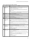
W1 W0
Measured pulse selection bits
Count clock selection bits
Reload mode selection bit
Operating mode selection bit
Timer output bit
Only applies to the pulse width measurement function (FC = "1").
0 0 High level
0 1 Low level
1 0 Rising edge to rising edge
1 1 Falling edge to falling edge
C1 C0
0 01 tinst
014 tinst
1 0 32 tinst
1 1 Do not use this setting.
t
inst
: Instruction cycle
TO
Read Write
0
Reads the current output
value.
Can be used to set the
output value when the
counter is stopped.
1
RM
Only applies to the interval timer function (FC = "0").
0 Reload timer mode
1 One-shot timer mode
FC
0 Operates as an interval timer function.
1 Operates as a pulse width measurement function.
R/W : Readable and writable
— : Unused
: Initial value
000-0000B