


176
CHAPTER 9 8-BIT SERIAL I/O
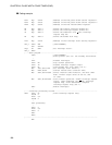
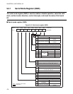
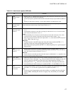
9.3.1 Serial Mode Register (SMR)
The serial mode register (SMR) is used to enable or disable operation, select the shift
clock, set the transfer direction, control interrupts, and check the state of 8-bit serial
I/O.
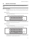
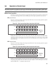
■ Serial mode register (SMR)
Figure 9.3-3 Serial mode register (SMR)
Address Bit 7 Bit 6 Bit 5 Bit 4 Bit 3 Bit 2 Bit 1 Bit 0 Initial value
001C
H
SIOF SIOE SCKE SOE CKS1 CKS0 BDS SST 00000000
B
R/W R/W R/W R/W R/W R/W R/W R/W
SST
Serial I/O transfer start bit
Serial data output enable bit
Shift clock output enable bit
Interrupt request enable bit
Interrupt request flag bit
Transfer direction selection bit
Read Write
0 Serial transfer stopped.
Stops/disables serial
transfer.
1 Serial transfer operating.
Starts/enables serial
transfer.
BDS
0 LSB first (starts transfer from the least significant bit)
1 MSB first (starts transfer from the most significant bit)
CKS1 CKS0 Shift cl ock sel ection bits SCK pin
0 0
Internal shift
clock
2 t
inst
Output
01 8 t
inst
Output
1 0 32 t
inst
Output
1 1 External shift clock Input
t
inst
: Instruction cycle
SOE
0 Functions P44/SO as the general-purpose I/O port.
1 Functions P44/SO as the serial data output pin.
SCKE
0
Functions P45/SCK as a general-purpose I/O port
or shift clock input pin.
1 Functions P45/SCK as the shift clock output pin.
SIOE
0 Disables interrupt request output.
1 Enables interrupt request output.
SIOF
Read Write
0
Transfer has not
completed.
Clears this bit.
1 Transfer has completed.
No effect.The bit does not
change
R/W : Readable and writable
: Initial value