


135
CHAPTER 7 8-BIT PWM TIMER
7.7 States in Each Mode during 8-bit PWM Timer Operation
This section describes the operation of the 8-bit PWM timer when the device goes to
sleep or stop mode, or an operation halt request occurs during operation.
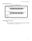
■ Operation during standby mode or operation halt
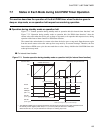
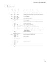
Figure 7.7-1 "Counter operation during standby mode or operation halt (for interval timer function)" and
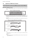
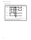
Figure 7.7-2 "Operation during standby mode or operation halt (for PWM timer function)" show the
counter value states when the device goes to sleep or stop mode, or an operation halt request occurs, during
operation of the interval timer function or PWM timer function.
The counter halts and maintains its current value when the device goes to stop mode. Operation starts again
from the stored counter value after wake-up from stop mode by an external interrupt. Therefore, the first
interval time or PWM wave cycle does not match the set value. Always initialize the 8-bit PWM timer after
wake-up from stop mode.
●
For interval timer function
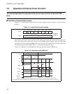
Figure 7.7-1 Counter operation during standby mode or operation halt (for interval timer function)
Counter value
COMR value (FF
H
)
FF
H
00
H
Timer cycle
Time
TIR bit
TPE bit
PWM pin
SLP bit
Cleared by the program
Stop request
Oscillation stabilization
delay time
Cleared by the operation halt.
Operation halts Operation restarts
(OE = "1")
(STBC register)
STP bit
(STBC register)
Sleep mode
Wake-up from sleep mode by IRQ2
"L" while counter is stopped.
*
Stop mode
Wake-up from stop mode by an external interrupt.
* : The PWM pin (PWM) goes to the high-impedance state during stop mode if the pin state specification bit in
the standby control register (STBC: SPL) is "1" ("H" level if pull-up is selected for PWM pin).
When the SPL bit is "0", the pin maintains its value prior to entering stop mode.