


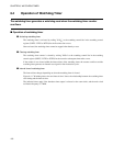

124
CHAPTER 7 8-BIT PWM TIMER
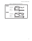
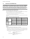
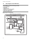
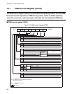
7.2 Block Diagram of 8-bit PWM Timer
The 8-bit PWM timer consists of the following six blocks:
• Count clock selector
• 8-bit counter
• Comparator circuit
• PWM generator and output controller
• PWM compare register (COMR)
• PWM control register (CNTR)
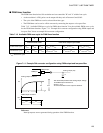
■ Block diagram of 8-bit PWM timer
Figure 7.2-1 Block diagram of 8-bit PWM timer
P/T P1 P0 TPE TIR OE TIE
Internal data bus
COMR
PWM compare register
IRQ2
Start
CLK
Clear
Over flow
8-bit
counter
Comparator circuit
Count clock
selector
X 1
X 16
X 64
PWM generator
and
output controller
Output
Pin
Output pin control bit
PWC timer output
1 t
inst
Timer/PWM
CNTR
8
8
P41/PWM
To UART
tinst: Instruction cycle (4/FCH)