


138
CHAPTER 7 8-BIT PWM TIMER
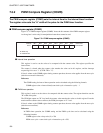
7.9 Program Example for 8-bit PWM Timer
This section gives program examples for the 8-bit PWM timer.
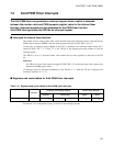
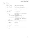
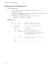
■ Program example for interval timer function
●
Processing description
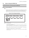
• Generates repeated interval timer interrupts at 2.5 ms intervals.
• Outputs a square wave to the PWM pin that inverts after each interval time.
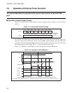
• With a main clock oscillation frequency F
CH
of 5 MHz, and the highest speed clock selected by the
speed-shift function (1 instruction cycle time = 4/F
CH
), the COMR register is set for an interval time of
approximately 5 ms (an internal clock period of 64 t
inst
is selected as the count clock). The COMR
register setting is calculated as follows:
COMR register value = 5 ms/(64 x 4/5 MHz) - 1 = 97 (061
H
)