


28
CHAPTER 3 CPU
●
Temporary accumulator (T)
The temporary accumulator is an auxiliary 16-bit arithmetic operation register used to perform arithmetic
operations with the data in the accumulator (A). The content of the temporary accumulator is treated as
word data (16-bit) for word-length arithmetic operations with the accumulator and as byte data (8-bit) for
byte-length arithmetic operations. For byte-length arithmetic operations, only the lower 8 bits of the
temporary accumulator (TL) are used and the upper 8 bits (TH) are not used.
Executing a transfer instruction to transfer data to the accumulator (A) automatically transfer the previous
content of the accumulator to the temporary accumulator. In this case also, a byte transfer leaves the upper
8 bits of the temporary accumulator (TH) unchanged. The content of the temporary accumulator after a
reset is indeterminate.
●
Index register (IX)
The index register is a 16-bit register used to hold the index address. The index register is used in
conjunction with a single byte offset value (-128 to +127). Adding the sign-extended offset value to the
index address generates the memory address for data access. The content of the index register after a reset
is indeterminate.
●
Extra pointer (EP)
The extra pointer is a 16-bit register used to hold a memory address for data access. The content of the
extra pointer after a reset is indeterminate.
●
Stack pointer (SP)
The stack pointer is a 16-bit register used to hold the address referenced during operations such as
interrupts, subroutine calls, and the stack save and restore instructions. The value of the stack pointer
during program execution is the address of the most recently saved data on the stack. The content of the
stack pointer after a reset is indeterminate.
●
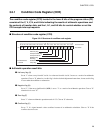
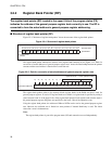
Program status (PS)
The program status is a 16-bit control register. The upper 8 bits contain the register bank pointer (RP)
which points to the address of the current general-purpose register bank.
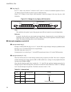
The lower 8 bits contain the condition code register (CCR) which contains flags indicating the current CPU
status. The two 8-bit registers which form the program status cannot be accessed independently (the
program status can only be accessed by the MOVW A,PS and MOVW PS,A instructions).
Refer to the F
2
MC-8L MB89600 series Programming Manual for details on using the dedicated registers.