


29
CHAPTER 3 CPU
3.2.1 Condition Code Register (CCR)
The condition code register (CCR) located in the lower 8 bits of the program status (PS)
consists of the C, V, Z, N, and H bits indicating the results of arithmetic operations and
the contents of transfer data, and the I, IL1, and IL0 bits for control whether or not the
CPU accepts interrupt requests.
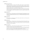
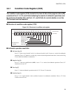
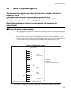
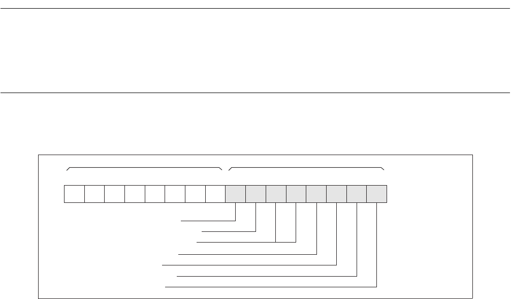
■ Structure of condition code register (CCR)
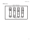
Figure 3.2-2 Structure of condition code register
■ Arithmetic operation result bits
●
Half-carry flag (H)
Set to "1" when a carry from bit 3 to bit 4 or a borrow from bit 4 to bit 3 occurs as a result of an arithmetic
operation. Clear to "0" otherwise. As this flag is for the decimal adjustment instructions, do not use this flag
in cases other than addition or subtraction.
●
Negative flag (N)
Set to "1" if the most significant bit (MSB) is set to "1" as a result of an arithmetic operation. Clear to "0"
when the bit is set to "0".
●
Zero flag (Z)
Set to "1" when an arithmetic operation results in "0". Clear to "0" otherwise.
●
Overflow flag (V)
Set to "1" if a signed numeric value overflows because of an arithmetic calculation. Clear to "0" if the
overflow does not occur.
Half-carry flag
Interrupt enable flag
Interrupt level bits
Negative flag
Zero flag
Overflow flag
Carry flag
Bit 15 Bit 14 Bit 13 Bit 12 Bit 11 Bit 10 Bit 9 Bit 8 Bit 7 Bit 6 Bit 5 Bit 4 Bit 3 Bit 2 Bit 1 Bit 0
R4 R3 R2 R1 R0 ———HIIL1IL0NZVC
CCR initial value
X011XXXX
B
RP CCR
PS
X: Indeterminate
- : Unused