


184
CHAPTER 9 8-BIT SERIAL I/O
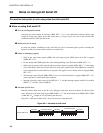
During this time, hold the external shift clock at the "H" level while waiting for the next data (idle state).
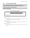
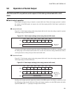
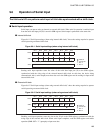
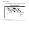
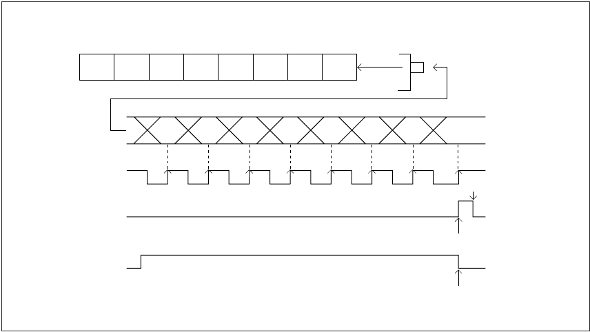
Figure 9.6-3 "8-bit serial input operation" shows the 8-bit serial input operation.
Figure 9.6-3 8-bit serial input operation
■ Operation at completion of serial input
The 8-bit serial I/O sets the interrupt request flag bit (SMR: SIOF = "1") and clears the serial I/O transfer
start bit (SMR: SST = "0") on the rising edge of the shift clock after the serial data of the eighth bit is input.
0123456 7
Bit 7
#7
Bit 6
#6
Bit 5
#5
SDR
Bit 4
#4
Bit 3
#3
Bit 2
#2
Bit 1
#1
Bit 0
#0
#7 #6 #5 #4 #3 #2 #1 #0
For MSB first
SI pin
Serial input
data
Shift clock
SIOF bit
Interrupt request
Cleared by the program.
SST bit
Automatically cleared
when transfer completes.