


195
CHAPTER 10 UART
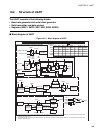
■ Selection of transfer clocks
The transfer clock can selected from the external clock (SCK pin), PWM timer or dedicated baud rate
generator by setting CS0 and CS1 bits of serial rate control register (SRC). In addition, the CR bit of SRC
and SMDE bit of serial mode control register 1 (SMC1) can determine which divider for the selected
transfer clock. Please refer to Table 10.1-2 "Clock ratio".
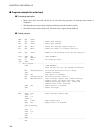
When using the dedicated baud rate generator, the input clock of the baud rate generator is selected by
PDS1 and PDS0 bits of serial mode control register 2 (SMC2). The ratio of dividing frequency is shown in
Table 10.1-3 "Dividing frequency of dedicated baud rate generator".
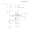
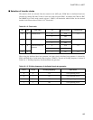
Table 10.1-2 Clock ratio
CS1 CS0 Clock input CR Asynchronous Synchronous
0 0 External clock 0 1/16 1/1
11/64
0 1 PWM timer 0 1/16 1/2
11/64
1 0 Dedicated baud rate
generator
0 1/16 1/2
11/64
11 -- 1/8 1/1
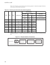
Table 10.1-3 Dividing frequency of dedicated baud rate generator
PDS1 PDS0 Dividing frequency Input clock
0 0 1/4 CPU operating clock
0 1 1/6 CPU operating clock
1 0 1/13 CPU operating clock
1 1 1/65 CPU operating clock