


125
CHAPTER 7 8-BIT PWM TIMER
●
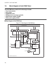
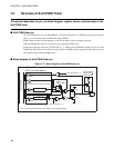
Count clock selector
Selects a count-up clock for the 8-bit counter from the three internal count clocks and the PWC timer
output cycle.
●
8-bit counter
The 8-bit counter counts up on the count clock selected by the count clock selector.
●
Comparator circuit
The comparator circuit has a latch to hold the COMR register value. The circuit latches the COMR register
value when the 8-bit counter value is "00
H
". The comparator circuit compares the 8-bit counter value with
the latched COMR register value, and detects when a match occurs.
●
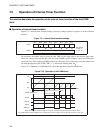
PWM generator and output controller
When a match is detected during interval timer operation, an interrupt request is generated and, if the
output pin control bit (CNTR: OE) is "1", the output controller inverts the output level of the PWM pin. At
the same time, the 8-bit counter is cleared.
When a match is detected during PWM timer operation, the PWM generator changes the output level of the
PWM pin from "H" to "L". The pin is set back to the "H" level when the next overflow occurs on the 8-bit
counter.
●
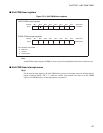
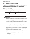
COMR register
The COMR register is used to set the value that is compared with the value of the 8-bit counter.
●
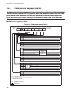
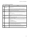
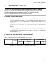
CNTR register
The CNTR register is used to select the operating mode, enable or disable operation, set the count clock,
control interrupts, and check the PWM status.
Setting the operation to PWM timer mode (P/T = "0") disables clearing of the 8-bit counter and generation
of interrupt requests (IRQ2) when the comparator circuit detects a match.