


183
CHAPTER 9 8-BIT SERIAL I/O
9.6 Operation of Serial Input
The 8-bit serial I/O can perform serial input of 8-bit data synchronized with a shift clock.
■ Serial input operation
Serial input can operate using an internal or external shift clock. When serial in operation is enabled, input
from the serial data input pin (SI) is stored in SDR register. Serial output is performed at the same time.
●
Internal shift clock
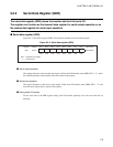
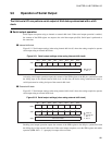
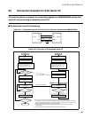
Figure 9.6-1 "Serial input settings (when using internal shift clock)" shows the settings required to operate
serial input using an internal shift clock.
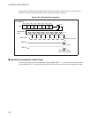
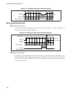
Figure 9.6-1 Serial input settings (when using internal shift clock)
Starting serial input operation stores the value of the serial data input pin (SI) to the SDR register,
synchronized with the rising edge of the selected internal shift clock. At this time, the device being
communicated with (a serial output) must have data set in the SDR register and be waiting for input of the
external shift clock.
●
External shift clock
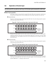
Figure 9.6-2 "Serial input settings (when using external shift clock)" shows the settings required to operate
serial input using an external shift clock.
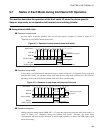
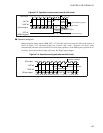
Figure 9.6-2 Serial input settings (when using external shift clock)
Enabling serial input operation stores the data on the SI pin to the SDR register, synchronized with the
rising edge of the external shift clock. When serial input completes, read the SDR register and enable
operation (SMR: SST = "1") promptly to input next data.
DDR4
SMR SIOF SIOE SCKE SOE CKS1 CKS0 BDS SST
1
other than "11"
1
SDR Stores the received data.
: Used bit
: Unused bit
1 : Set "1"
0 : Set "0"
Bit 7 Bit 6 Bit 5 Bit 4 Bit 3 Bit 2 Bit 1 Bit 0
XXX X
X
0XXX
X
DDR4
SMR SIOF SIOE SCKE SOE CKS1 CKS0 BDS SST
SDR Shows the received data.
: Used bit
: Unused bit
1 : Set "1"
0 : Set "0"
Bit 7 Bit 6 Bit 5 Bit 4 Bit 3 Bit 2 Bit 1 Bit 0
0XX X0 XXX
X
0 111
X