


166
CHAPTER 8 PULSE WIDTH COUNT TIMER (PWC)
●
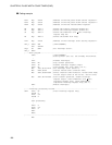
Coding example
PCR1 EQU 0014H ; Address of the PWC pulse width control register 1
PCR2 EQU 0015H ; Address of the PWC pulse width control register 2
RLBR EQU 0016H ; Address of the PWC reload buffer register
EN EQU PCR1:7 ; Define the counter operation enable bit.
IE EQU PCR1:5 ; Define the interrupt request enable bit.
UF EQU PCR1:2 ; Define the underflow (01H 00H) interrupt
request flag bit.
BF EQU PCR1:0 ; Define the buffer full flag.
ILR1 EQU 007CH ; Address of the interrupt level setting register 1
INT_V DSEG ABS ; [DATA SEGMENT]
ORG 0FFF4H
IRQ3 DW WARI ; Set interrupt vector.
INT_V ENDS
;-----Main program----------------------------------------------------------------
CSEG ; [CODE SEGMENT]
; Stack pointer (SP) etc. are already initialized.
:
CLRI ; Disable interrupts.
CLRB EN ; Stop counter operation.
CLRB IE ; Disable interrupt request output.
CLRB BF ; Clear buffer full flag (PCR1: bit 0).
MOV ILR1,#10111111B ; Set interrupt level (level 2).
MOV RLBR,#075H ; Counter reload value (interval time)
MOV PCR2,#00001000B ; Select interval timer function, reload timer mode,
initial output value of the TO bit, and 32 tinst.
MOV PCR1,#11100000B ; Start counter operation, enable interrupt
request output, clear underflow (01H 00H)
interrupt request flag, clear measurement
completion interrupt request flag (bit 1).
SETI ; Enable interrupts.
:
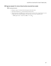
;-----Interrupt processing routine------------------------------------------------
WARI CLRB UF ; Clear interrupt request flag.
PUSHW A
XCHW A,T
PUSHW A
:
User processing
:
POPW A
XCHW A,T
POPW A
RETI
ENDS
;---------------------------------------------------------------------------------
END