


122
CHAPTER 7 8-BIT PWM TIMER
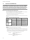
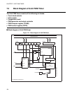
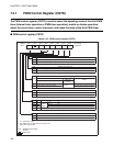
7.1 Overview of 8-bit PWM Timer
The 8-bit PWM timer can be selected to function as either an interval timer or PWM timer
with 8-bit resolution. The interval timer function counts up in synchronous with PWC
output clock or one of three internal count clocks. Therefore, an 8-bit interval timer time
can be set and the output can be used to generate variable frequency square waves.
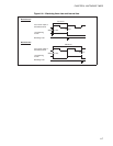
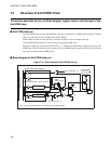
■ Interval timer function (square wave output function)
The interval timer function generates repeated interrupts at variable time intervals.
Also, as the 8-bit PWM timer can invert the output level of the pin (PWM) each time an interrupt is
generated, the 8-bit PWM timer can output a variable frequency square waves.
• The interval timer can operate with a cycle among 1 and 2
8
times the count clock cycle.
• The count clock can be selected from four different clocks.
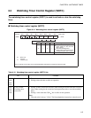
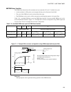
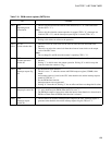
Table 7.1-1 "Interval time and square wave output range" lists the range for the interval time and square
wave output.
Reference:
[Calculation example for the interval time and square wave frequency]
In this example, the main clock oscillation frequency (F
CH
) is 5 MHz, the PWM compare register
(COMR) value is set to "DD
H
(221)", and the count clock cycle is set to 1 t
inst
. In this case, the interval
time and the frequency of the square wave output from the PWM pin (where the PWM timer operates
continuously and the value of the COMR register is constant) are calculated as follows.
Table 7.1-1 Interval time and square wave output range
Count clock cycle Interval time Square wave output (Hz)
1
Internal count
clock
1 t
inst
1 t
inst
to 2
8
t
inst
1/(2 t
inst
) to 1/(2
9
t
inst
)
2
2
4
t
inst
2
4
t
inst
to 2
12
t
inst
1/(2
5
t
inst
) to 1/(2
13
t
inst
)
3
2
6
t
inst
2
6
t
inst
to 2
14
t
inst
1/(2
7
t
inst
to 1/(2
15
t
inst
)
4
PWC timer
output cycle
2 t
inst
to 2
9
t
inst
2 t
inst
to 2
17
t
inst
1/(2
2
t
inst
) to 1/(2
18
t
inst
)
2
3
t
inst
to 2
11
t
inst
2
3
t
inst
to 2
19
t
inst
1/(2
4
t
inst
) to 1/(2
20
t
inst
)
2
6
t
inst
to 2
14
t
inst
2
6
t
inst
to 2
22
t
inst
1/(2
7
t
inst
) to 1/(2
23
t
inst
)
t
inst
: Instruction cycle
Interval time = (1 x 4/F
CH
) x (COMR register value + 1)
= (4/5 MHz) x (221 + 1)
= 177.6 s
Output frequency = F
CH
/ (1 x 8 x (COMR register value + 1))
= 5 MHz / (8 x (221 + 1))
= 2.8 kHz