


204
CHAPTER 10 UART
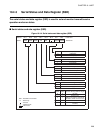
10.4 UART Registers
This section describes the registers of the UART.
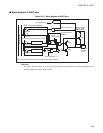
■ UART registers
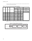
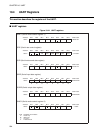
Figure 10.4-1 UART registers
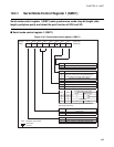
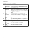
SMC1 (Serial mode control register 1)
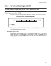
SRC (Serial rate control register)
SSD (Serial status and data register)
SIDR (Serial input data register)
SODR (Serial output data register)
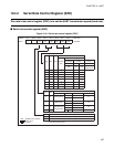
SMC2 (Serial mode control register 2)
Address Bit 7 Bit 6 Bit 5 Bit 4 Bit 3 Bit 2 Bit 1 Bit 0 Initial value
0020
H
PEN SBL MC1 MC0 SMDE SCKE SOE 00000-00
B
R/W R/W R/W R/W R/W R/W R/W
Address Bit 7 Bit 6 Bit 5 Bit 4 Bit 3 Bit 2 Bit 1 Bit 0 Initial value
0021
H
CR CS1 CS0 RC2 RC1 RC0 --011000
B
R/W R/W R/W R/W R/W R/W
Address Bit 7 Bit 6 Bit 5 Bit 4 Bit 3 Bit 2 Bit 1 Bit 0 Initial value
0022
H
RDRF ORFE TDRE TIE RIE TD8/TP RD8/RP 00100-1X
B
RRRR/WR/W R/WR
Address Bit 7 Bit 6 Bit 5 Bit 4 Bit 3 Bit 2 Bit 1 Bit 0 Initial value
0023
H
XXXXXXXX
B
RRRRRRRR
Address Bit 7 Bit 6 Bit 5 Bit 4 Bit 3 Bit 2 Bit 1 Bit 0 Initial value
0023
H
XXXXXXXX
B
WWWWWWWW
Address Bit 7 Bit 6 Bit 5 Bit 4 Bit 3 Bit 2 Bit 1 Bit 0 Initial value
0024
H
PSEN RSEL PDS1 PDS0 --1-0-00
B
R/W R/W R/W R/W
R/W : Readable and writable
R : Read-only
W : Write-only
— : Unused
X : Indeterminate